audio amplifier circuit diagram using ic tda2030 Wiring Diagram and Schematics
Step 1: Component List To make this powerful amplifier circuit, we need to use some electronics components. All components with PCB circuit, you can order from JLCPCB. They offer us best quality PCB circuit in a very cheap price. Component List - 1. Sound IC - TDA 2030 2. Capacitor - 10µf/ 50v 1µf/ 50v 2. Resistor - 220 Ω 680 Ω 18 K Ω 3.

TDA2030 Amplifier Circuit Unleash Crystal Clear Sound! Electro Gadget
No Minimum Order Necessary And Free Shipping on Orders over $60 AUD! Shop Today! Competitive Pricing on Millions of Electronic Components. Request a Quote Today.
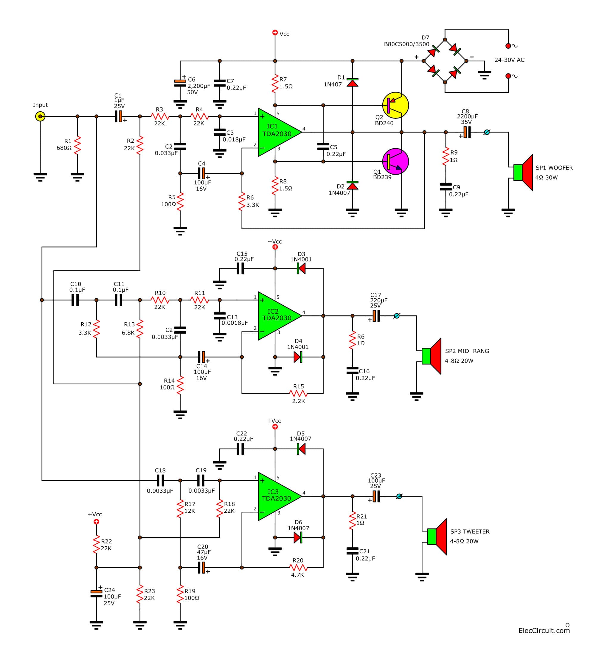
Tri Band Amplifier Circuit Project with Crossover network using TDA2030
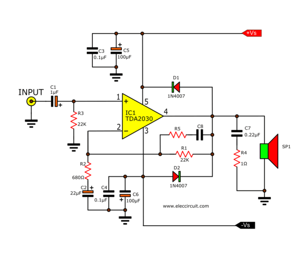
The TDA2030 is a monolithic integrated circuit in a pentawatt package and is intended for use as a low-frequency class AB amplifier. Its high output power enables it to drive larger speakers with ease. Circuit Diagram of TDA2030 Amplifier Single Supply
Tda2030 Audio Amplifier Pinout Diagram Features Datasheet Vrogue
Above is the circuit Diagram for this TDA2030 based Amplifier Circuit. We have connected a 2.2uf capacitor in series to the non-inverting pin of the TDA2030, here it is acting as the High Pass Filter. So that it allows only the high frequency audio signal. There is a resistor (R4) between pin 2 and 4 we called that resistor as Feedback Resistor.
2030 Ic 2.1 Amplifier Circuit Diagram
The TDA2030 integrated circuit is the ideal choice for creating the amplifier circuit. Because it is a low-cost, simple-to-use integrated circuit, appropriate for electronic novices. This circuit is built with a variety of electronic components. Turning up the level on this circuit allows you to hear the sound.

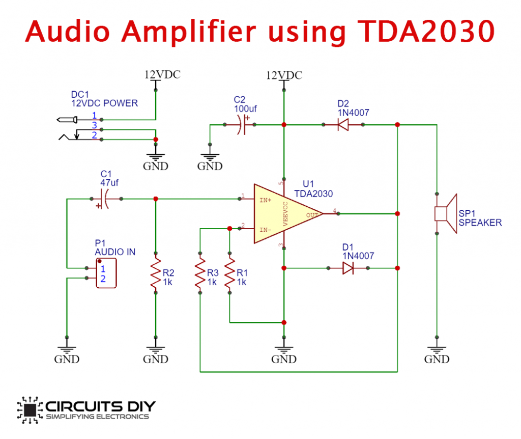
Power Amplifier Circuit using IC TDA2030
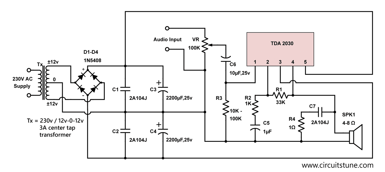
Step 1: Tda2030 TDA2030 amplifier circuit 12v, it is possible to operate the TDA2030 amplifier circuit in 12 volts, but we should follow the instruction to building properly functioned 12v TDA2030 amplifier Ask Question Step 2: Circuit Diagram and Working
TDA2030 Bridged Subwoofer amplifier circuit Amplifier Circuits
The TDA2030 is a monolithic integrated circuit in the Pentawatt ® package, intended for use as a low frequency class-AB amplifier. Typically it provides 14 W output power (d = 0.5%) at 14 V/4 Ω. At ±14 V or 28 V, the guaranteed output power is 12 W on a 4 Ω load and 8 W on an 8 Ω (DIN45500).
Tda2030 Audio Amplifier Circuit
Find the deal you deserve on eBay. Discover discounts from sellers across the globe. No matter what you love, you'll find it here. Search Mini-circuits amplifier and more.
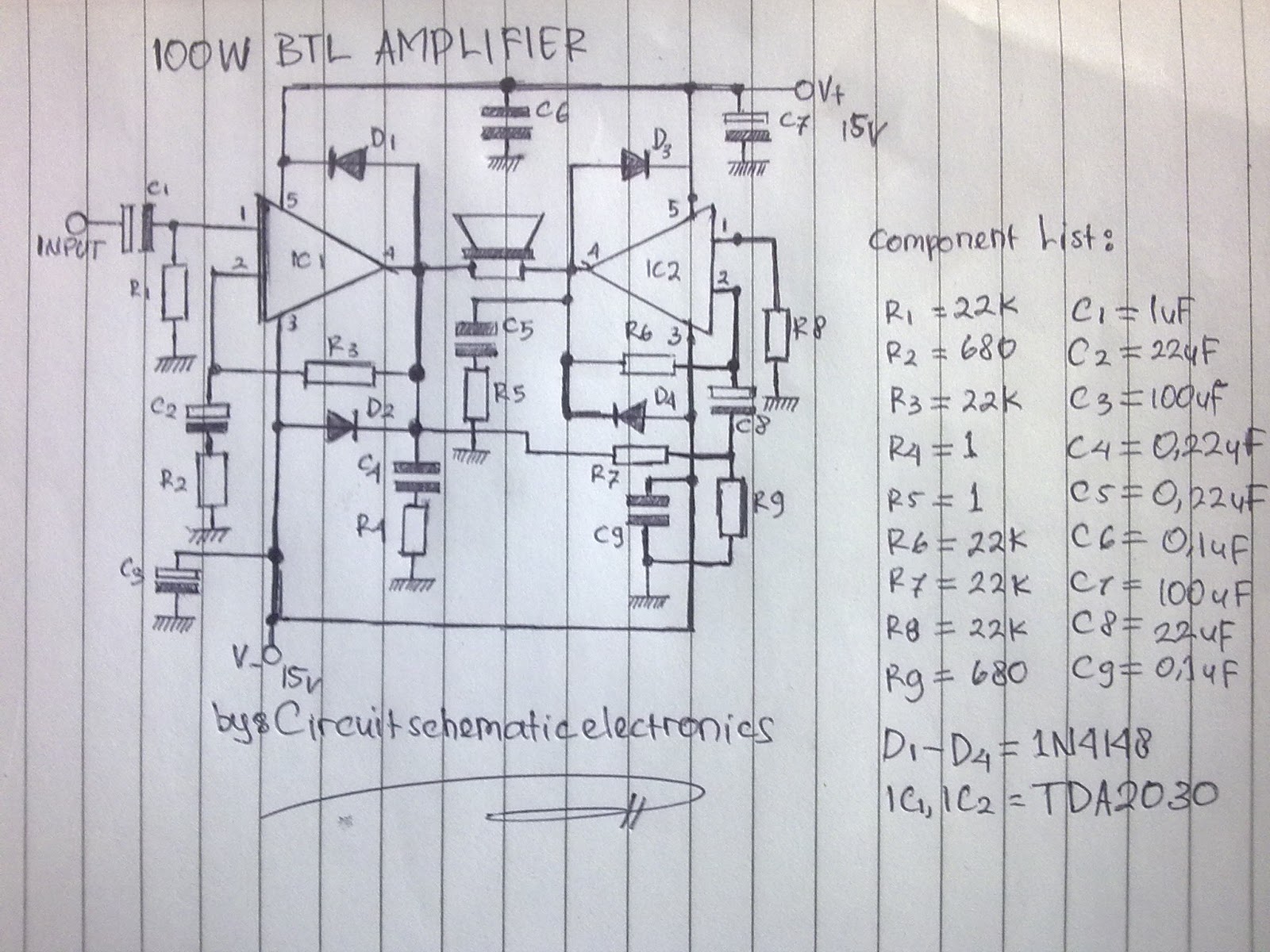
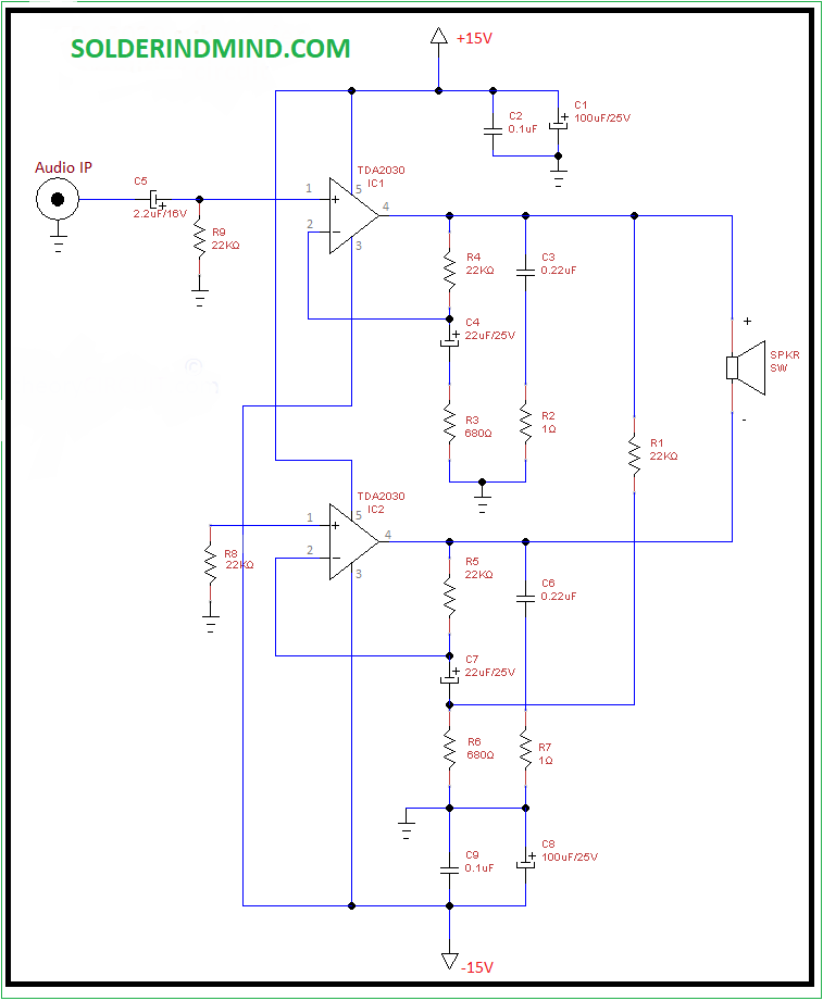
100W BTL TDA2030 amplifier circuit Electronic Circuit
TDA2030 is a monolithic integrated circuit in Pentawatt package, intended for use as a low frequency class AB amplifier. It provides 14W output power (d = 0.5%) at 14V/4Ω at ± 14V or 28V, the guaranteed output power is 12W on a 4Ω load or 8W on a 8Ω
Tda2030 Amplifier Circuit Diagram Pcb Tda2030 amplifier circuit diagram with PCB board
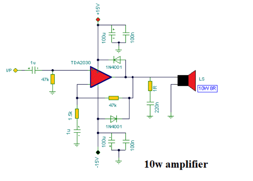
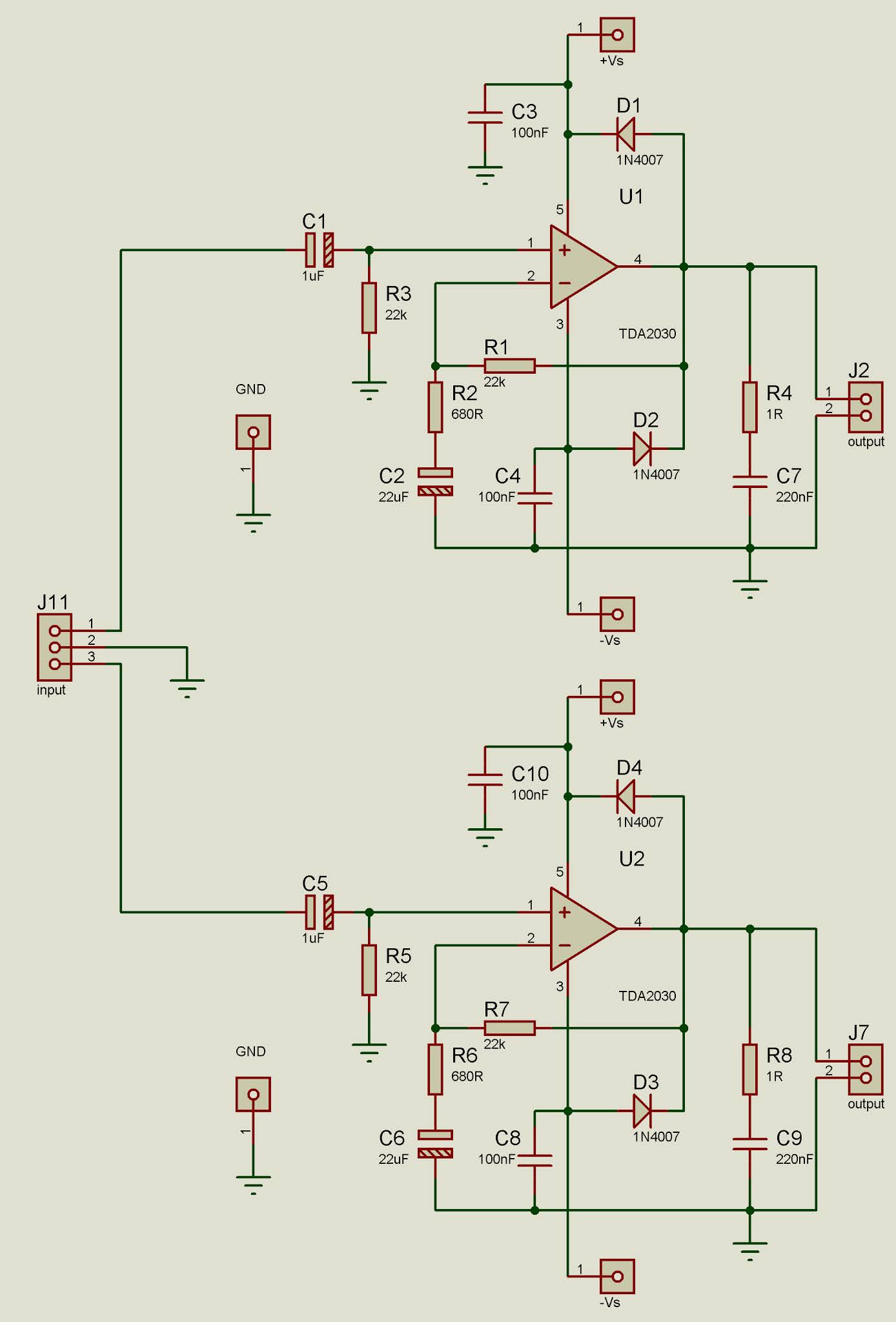
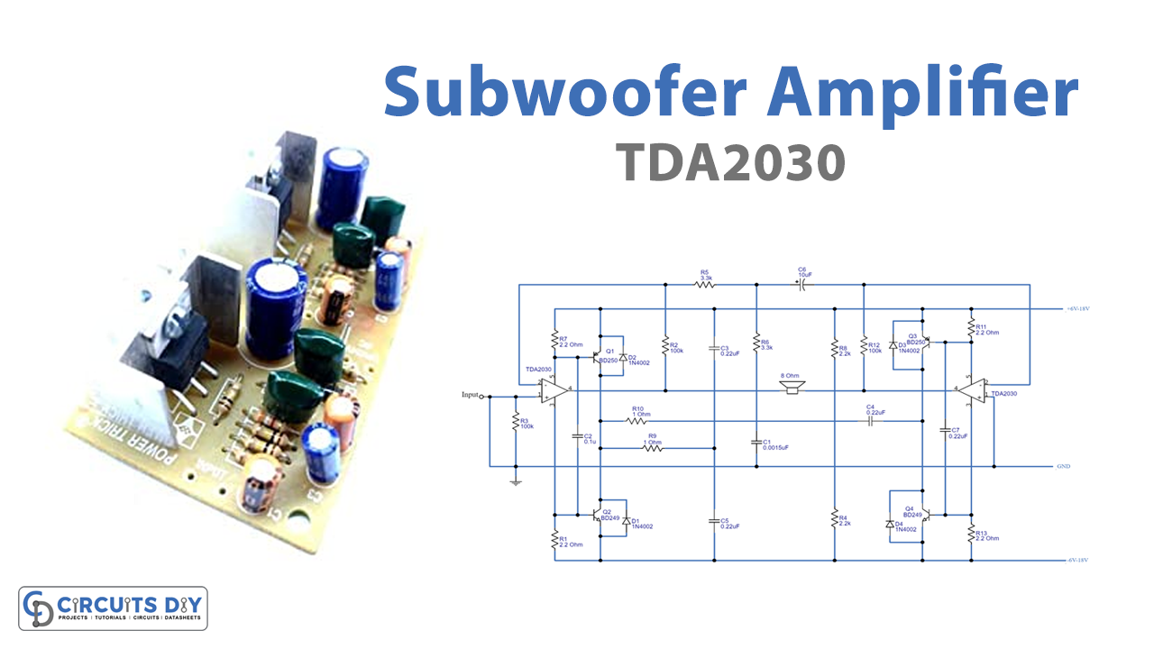
How it works Normally, TDA2030 is an integrated circuit that uses as a low-frequency class AB amplifier. Typically it provides 14W output power at ± 14V. Circuit diagram of 35 watts Bridge Amplifier using TDA2030 However, you can get more 35W output on TDA2030 in a bridged connection with a +- 15V power supply.
TDA2030 amplifier circuit singlesupply connection method circuit Amplifier_Circuit Circuit
Definition: The TDA2030 is a monolithic IC, available in Pentawatt package. This IC can be used as a low-frequency amplifier and generates 14W of o/p power. This IC includes high o/p current, low harmonic as well as crossover distortion. And also includes the protection system from the short-circuit & very high temperature. Features
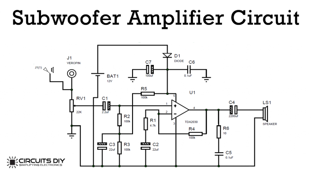
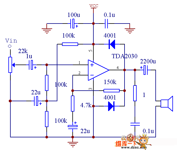
Subwoofer Amplifier Circuit using IC TDA2030
Tda2030 IC specifications. The tda2030a is a monolithic integrated circuit. is available in the petawatt packaging. Typically the mice will provide the 14 watts power output 14 volt,4 ohms. The guaranteed power output of the integrated circuit is 12 watts. This will be depending on the quality of the IC. Supply voltages plus or minus 18 (36v.
TDA2030 Subwoofer Amplifier Circuit
DESCRIPTION The TDA2030 is a monolithic integrated circuit in Pentawatt® package, intended for use as a low frequency class AB amplifier. Typically it provides 14W output power (d = 0.5%) at 14V/4 Ω; at ± 14V or 28V, the guaranteed output power is 12W on a 4Ω load and 8W on a 8Ω (DIN45500).
Tda2030 with transistor amplifier circuit Soldering Mind
Related Posts TDA2030 Datasheet Which the SGS said that it is a great power amplifier IC on 5 pins form. And, setting a circuit on a class AB power amplifier. The TDA2030 has high output current and very low harmonic and crossover distortion. Also, This device has the short-circuit and the too high-temperature protection system.
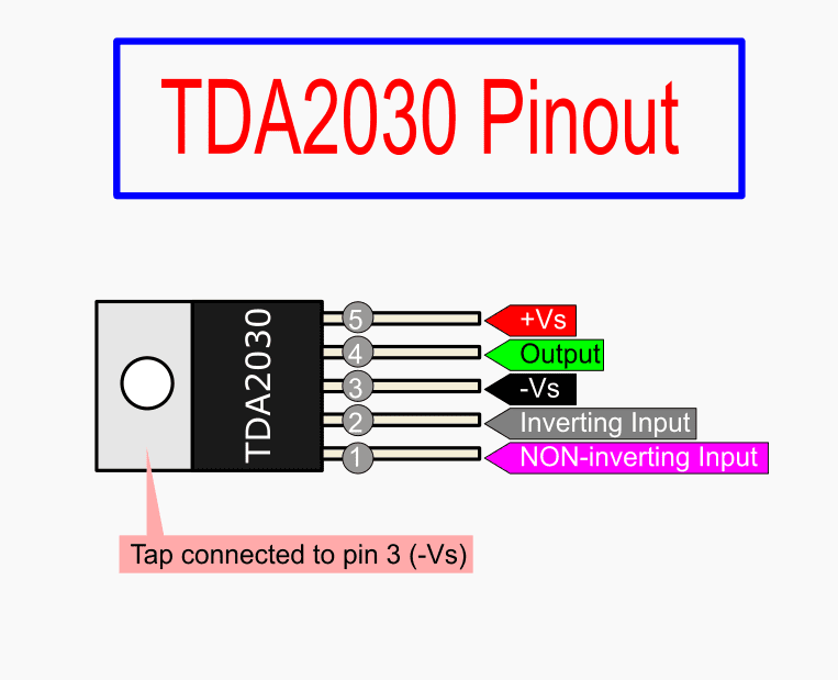
TDA2030 Datasheet Audio Amplifier Circuits Pinout
Or other useful amplifier circuit diagrams are quite abundant in Internet as TDA2030 was used to very popular audio IC chip for amplifier DIY before. For example, the following web page shows diverse and detail instructions for making amplifier with the TDA2030 chip. https://www.eleccircuit.com/tda2030-audio-amplifie.

200 Watt Subwoofer Amplifier Circuit Diagram
3.4 40W Power Amplifier Circuit . Figure 6 is a 40W power amplifier circuit made by TDA2030 power amplifier integrated block and BD907/908: Figure 6 40W power amplifier circuit made by TDA2030. 3.5 High-fidelity Active Speaker Circuit . A high-fidelity active speaker circuit designed with TDA2030, the circuit diagram is shown in Figure 7. Using.