
The 25+ best Hydraulic cylinder ideas on Pinterest Mechanical
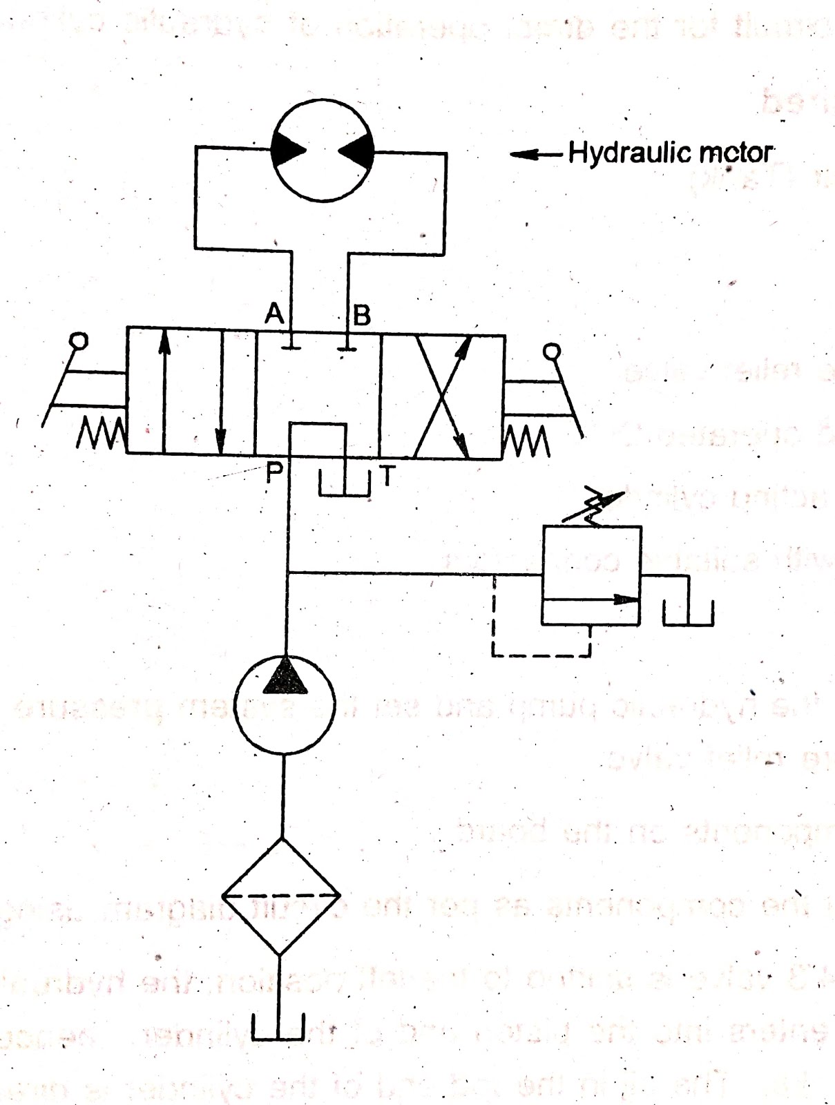
On this page, Carr Lane ROEMHELD provides a comprehensive table outlining the definitions of each symbol used in a hydraulic diagram. Engineers can use this page as a reference to determine common schematic symbols used in fluid power, hydraulics, pneumatics, diagrams and circuits. Basic Symbols Representing Hydraulic Components

35 How To Rebuild Hydraulic Cylinder Diagram Wiring Diagram List
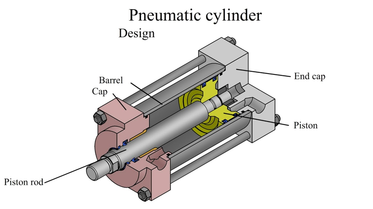
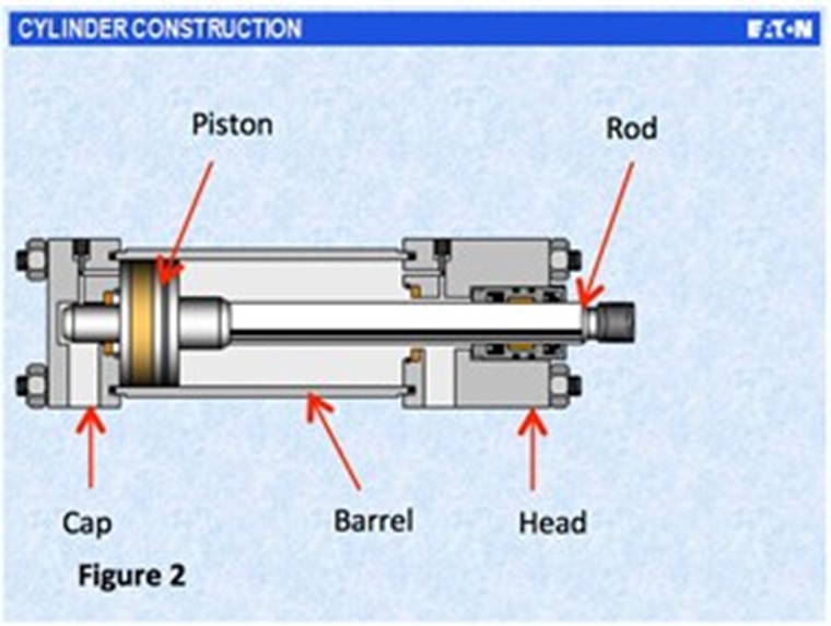
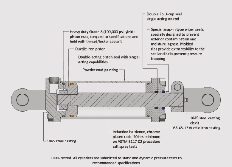
A hydraulic cylinder has eight basic components; the clevis, gland, port (s), barrel, rod, piston, the end cap, and the seal. When combined, these parts allow the hydraulic cylinder to pressurise fluid that mobilises a piston to generate power for a machine.
Hydraulic Cylinder Working Principle
Hydraulic Advantages. Hydraulics has many advantages not always found in electrical and mechanical type drives. Hydraulic cylinders and motors can be operated at variable speeds. By varying the volume flowing into the actuator (cylinder or motor) the speed is changed. The hydraulic cylinder or motor can be stalled under a load.
Hydraulic Cylinder Hyspecs Hydraulics Australia
A hydraulic cylinder is the actuator or 'motor' side of the system. The 'generator' side of the hydraulic system is the hydraulic pump which brings in a fixed or regulated flow of oil to the bottom side of the hydraulic cylinder, to move the piston rod upwards. The piston pushes the hydraulic oil in the other chamber back to the reservoir.
Hydraulic Cylinders, Cylinder Parts and Hydraulic System Parts Supplier
The basic drawn lines, cylinder symbols, ejector symbols, and the Do Not Scale note are just a handful of items that are particular to engineering drawings for hydraulics.. Cylinders do the major work in a hydraulic system but in a hydraulic press, an ejector is also needed. Both components utilize the same basic symbol and it's another.

If it’s an older system, it could be that the hydraulic cylinder is
1.3 Hydraulic Cylinders. Define the term actuator and give examples of a rotational electrical actuator and a linear hydraulic actuator. Draw a pictorial diagram of a double acting hydraulic cylinder. Identify the barrel, piston, rod, cap end plate, rod end plate, rod wiper, cap end port, and rod end port. NOTE: the rod end is often called the.

HYDRAULIC SYSTEM FOR BEGINNERS Mechanical Engineering Professionals
series 2A air cylinders. Optional for series 2H, 3L & VH hydraulic cylinders. Hi-Load Type Piston Optional on series 2H & VH hydraulic cylinders. Not available on series 2A & 3L cylinders. Series 2A Series 2H, 3L & VH S eries 2A & 3L S eries 2H & VH Bore Contains 2 Ea. Contains 2 Ea. Cylinder Body Material Size Symbol 47 Symbol 47 Brass Steel.
Peninsular Cylinder Co. cylinder repair, hydraulic cylinder repair
1. Identifying the line types In a hydraulic schematic, each line type has a unique meaning. In addition, colors can be added to indicate purpose of the line. In the figure below, all of the basic line types are shown. The basic line is a solid line that represents a working pressure hose or tube.

Hydraulic Cylinder Parts Diagram General Wiring Diagram
The hydraulic cylinders on this excavator operate the machine's linkages. Hydraulic cylinders in a hot press of a particle board machine. A hydraulic cylinder (also called a linear hydraulic motor) is a mechanical actuator that is used to give a unidirectional force through a unidirectional stroke. It has many applications, notably in construction equipment (engineering vehicles.
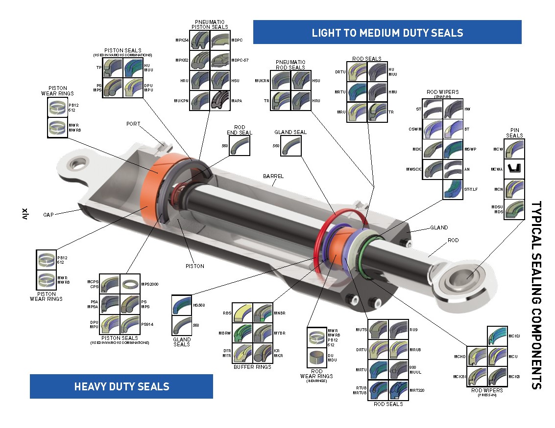
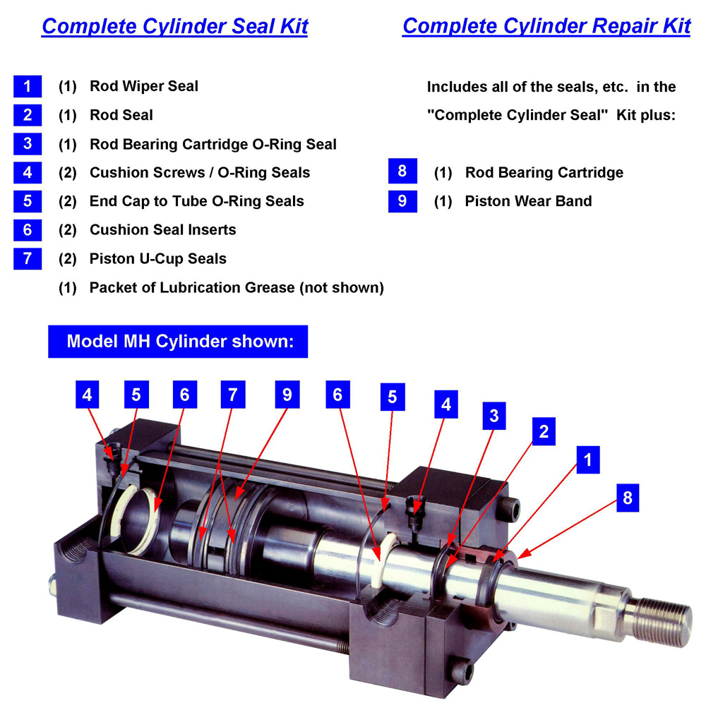
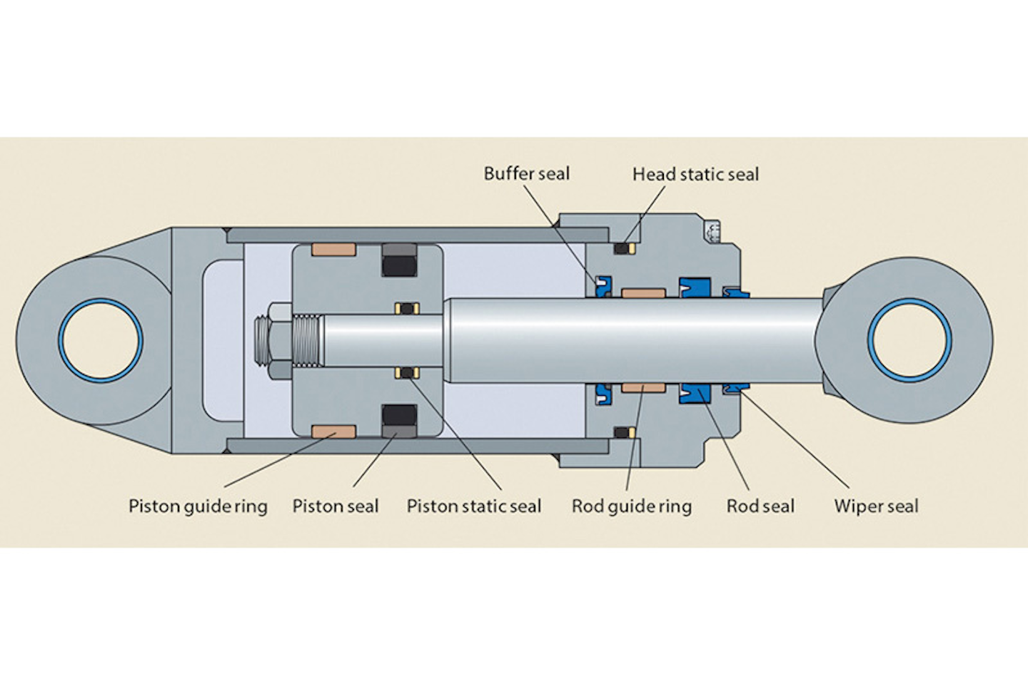
The Function of Seals In a Hydraulic Cylinder หน้าที่ของซีลในกระบอกไฮดรอลิก
2. Remove the external steel wire ring. 3. Remove any dirt that may have accumulated on the cylinder head. 4. Using the mallet and punch, push the head into the cylinder tube until the. is fully exposed. This will also move the internal wire ring into its removal position. 5.
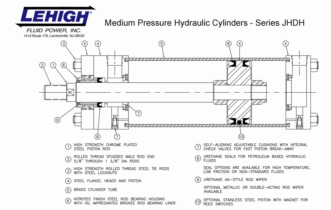
Hydraulic Cylinders Lehigh Fluid Power
A hydraulic cylinder schematic diagram provides a visual representation of the different components and fluid flow paths within a hydraulic cylinder system. By studying these diagrams, engineers and technicians can gain valuable insights into the functionality and performance of hydraulic cylinders.
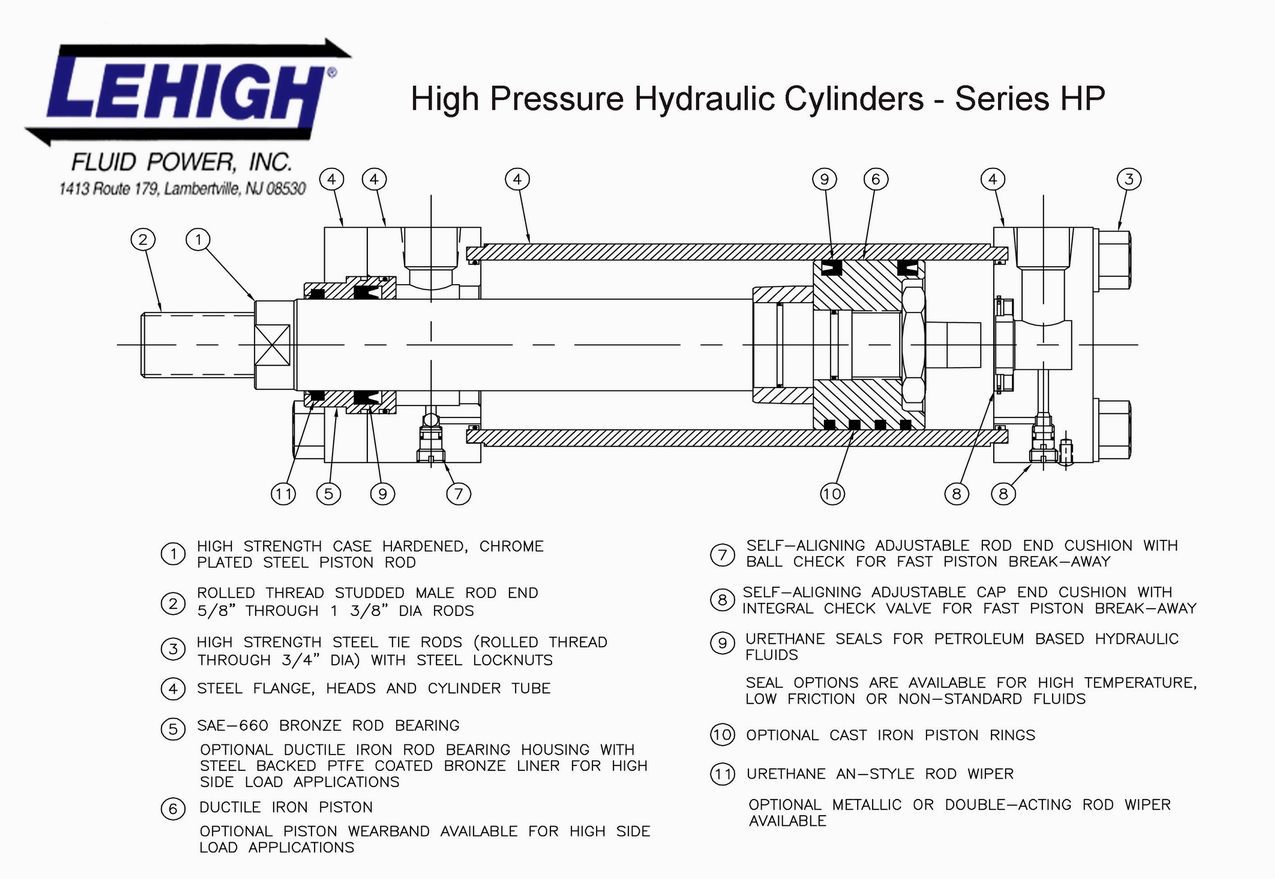
Hydraulic Cylinders Lehigh Fluid Power
The function of a cylinder in a fluid power system is to convert energy in the fluid stream into an equivalent amount of mechanical energy. Its power is delivered in a straight-line, push-pull motion. Graphic Symbols: Following diagram illustrates standard ANSI (American National Standards Institute) graphic symbols for use in circuit diagrams.

Hydraulic Cylinder Equations Tessshebaylo
How does the hydraulic cylinder work? Гидравлика и пневматика 1.7K Likes 2018 Apr 18 How does the hydraulic cylinder work? A hydraulic cylinder has the following parts: piston, rod, seals,.
Machine Drawing Double acting cylinder Pneumatic Circuit
Simple Hydraulic System Hydraulic Schematic Symbols Accumulator Cylinder Double acting Directional Control Valve (manually operated) Dump Pumps Hydraulic System Components: Gear Pump Hydraulic Pump Symbol Hydraulic System Components : Accumulator Accumulator symbol Hydraulic System Components : Directional Control Valve
Sealing the deal in hydraulic cylinders PI Process Instrumentation
Fτ = P∏ (r12 - r22 ) Where: Fτ is the resultant force. P is the pressure distributed load on the surface. ∏ is pi, approximately equal to 3.14159. r1 is the radius of the piston. r2 is the radius of the piston rod. In hydraulic cylinders, the force can easily be multiplied or divided throughout the system.

The Parts of a Hydraulic Cylinder It Still Runs Your Ultimate Older
The term cylinder is commonly used to describe a device that gives linear force output and movement. A cylinder may also be referred to as a linear actuator. Cylinders are broken down into two main categories: pneu-matic and hydraulic. Pneumatic cylinders can be operated by several types of gases; however, compressed air is by far the most common.